Article 2 : Calculation methods for glass panels
Calculation methods for glass panels
Moving the glazing under load (Service Limit State)
GENERAL
The calculation methods for the design of mechanical elements have evolved significantly in recent decades. It was in the 19th century that Continuum Mechanics (CM) began to develop, and a century later, the theorization of the Finite Element Method (FEM) emerged. The Finite Element Method (FEM) is a numerical technique used to solve engineering and physics problems involving complex structures. The theorization of the Finite Element Method involves defining the mathematical foundations on which this method is based. This theorization, coupled with the continuous improvement of numerical solution methods and the continuous improvement in processor power (Moore’s Law), has brought about a turning point in modern mechanical design methods.
Previously, structural calculations were always done by hand using tables (graphical models) and beam formulas from the strength of materials. With modern means and the use of dedicated finite element analysis software, it is now possible to perform calculations on complex geometries and predict mechanical behavior locally and accurately. Just imagine what a structure similar to the Eiffel Tower could look like today with modern resources! With more precise calculation models, it is possible, for example, to refine the behavior of glass in support zones, contact zones, drilling zones, and accurately determine stress levels in the glass and fixings. When well-mastered, these new techniques are very interesting as they reduce the number of assumptions and, ultimately, limit overdesign of structures and glass thicknesses.

In general, the calculation methods for sizing glass panels are carried out using software that employs advanced mathematical models. It is possible to predict the movements of glass panels on facades and calculate their mechanical stresses. These calculations enable the optimization of structures and glass panels for top-notch projects!
In general, the calculation methods for sizing glass panels are carried out using software that employs advanced mathematical models. It is possible to predict the movements of glass panels on facades and calculate their mechanical stresses. These calculations enable the optimization of structures and glass panels for top-notch projects!
CALCULATION OF AN ATTACHED EXTERIOR GLAZING (AEG)
The commonly used method for sizing and predicting the strength of glass supported on one or two sides is to employ a beam bending model.
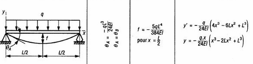
Table 1: Bending beam form from strength of materials formulae
CALCULATION OF AN ATTACHED EXTERIOR GLAZING (AEG)
The commonly used method for sizing and predicting the strength of glass supported on one or two sides is to employ a beam bending model.
Table 1: Bending beam form from strength of materials formulae
However, verifying an attached exterior glazing requires very specific assumptions, especially for assessing stress in the glass at support points. The assumption of a beam bending model is much less suitable for glass supported by fixing points. In France, tables (calculation models) are used in conjunction with tests to dimension Attached Exterior Glazings (AEGs) in most common cases. Furthermore, for glass with unusual shapes, dimensions, or positions of fixing points, the use of finite element analysis software is recommended.
However, verifying an attached exterior glazing requires very specific assumptions, especially for assessing stress in the glass at support points. The assumption of a beam bending model is much less suitable for glass supported by fixing points. In France, tables (calculation models) are used in conjunction with tests to dimension Attached Exterior Glazings (AEGs) in most common cases. Furthermore, for glass with unusual shapes, dimensions, or positions of fixing points, the use of finite element analysis software is recommended.
Using finite element analysis software:
The method involves taking a computer-drawn model, discretizing (numerically dividing) the panel into small elements, commonly known as meshing operation, and applying the desired support and loading conditions. Subsequently, the software solves the equilibrium equations (partial differential equations) and stores the results in the form of a table for each small element created during the meshing operation. This allows for recording in a spreadsheet and obtaining the displacements, forces, and stress levels for each small element of the glass.
All of these calculation methods enable us to study the feasibility of projects involving glass railings, cladding, or other glass fixtures. See the example below:
For the calculation of an Attached Exterior Glazing (AEG), we rely on existing assumptions that stem from previously conducted tests. However, for unusual glass structures or panels, it’s a different story. Specific methods will be employed to analyze each part of the glass in order to calculate the forces acting upon it.
For the calculation of an Attached Exterior Glazing (AEG), we rely on existing assumptions that stem from previously conducted tests. However, for unusual glass structures or panels, it’s a different story. Specific methods will be employed to analyze each part of the glass in order to calculate the forces acting upon it.
EXAMPLE OF ATTACHED EXTERIOR GLAZING CALCULATION
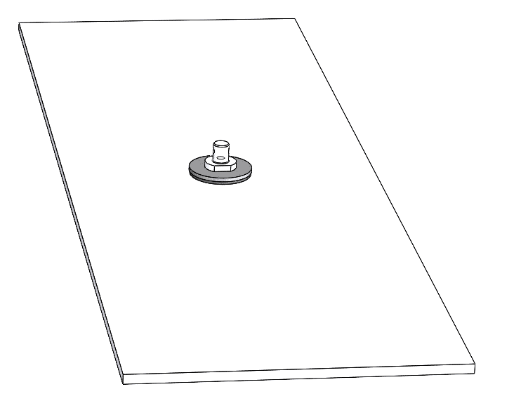
In the following example, we will study the bending stresses in VEA glazing for a very specific configuration. For example: a glass panel is held in place by just 3 fixing points and subjected to a wind pressure of 1000 Pa. The model is drawn in CAD, followed by meshing and the application of fixing points to hold the glass in place (boundary conditions).
In the following example, we will study the bending stresses in VEA glazing for a very specific configuration. For example: a glass panel is held in place by just 3 fixing points and subjected to a wind pressure of 1000 Pa. The model is drawn in CAD, followed by meshing and the application of fixing points to hold the glass in place (boundary conditions).
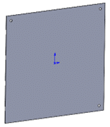
Computer-Aided Design Modeling
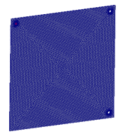
Meshing Operation
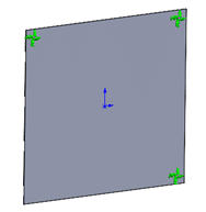
Application of Boundary Conditions
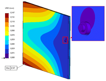
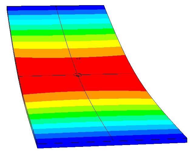
The results for glass deformation initially show that they are limited to 15mm. Furthermore, the bending stresses (outside the support zone) are lower than the allowable stresses for the glass (including load and material safety factors). The verification is carried out according to the criteria outlined in CSTB’s document 3574_v2.
The results for glass deformation initially show that they are limited to 15mm. Furthermore, the bending stresses (outside the support zone) are lower than the allowable stresses for the glass (including load and material safety factors). The verification is carried out according to the criteria outlined in CSTB’s document 3574_v2.
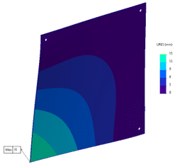
Glass Displacement
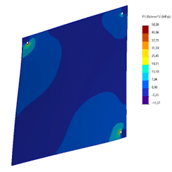
Bending Stresses* in the Glass
The dimensions of the glass (height, width, thickness), excluding drilling zones, are suitable for the project. However, it can be observed that localized stresses appear at the drilling locations. A more detailed analysis must therefore be conducted to assess the stresses in these areas.
To analyze the stresses in the glass’s drilling zones, a more detailed modeling of the glass and the contacting parts is performed. The materials, geometry of the parts, and contacts are defined in a precise numerical simulation model to accurately assess the stresses in the glass.
All the calculations performed are represented by colors and can be visualized on the image:
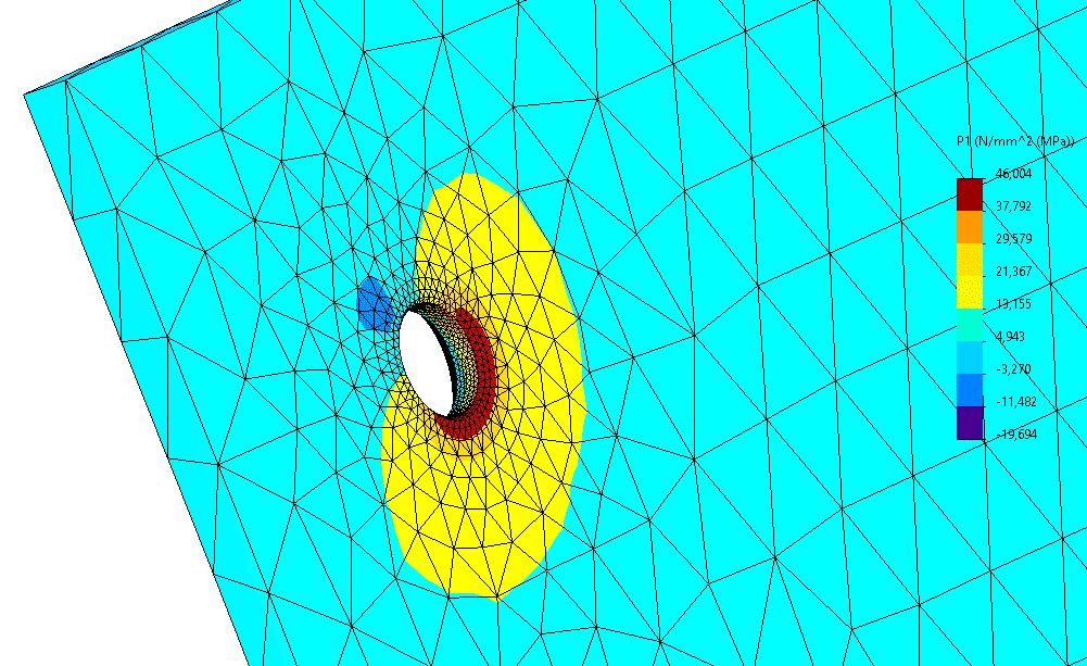
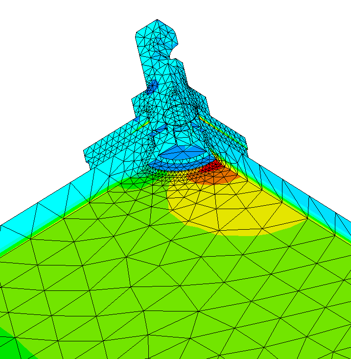
Main tensile stresses displayed at the drilling of an attached external glazing
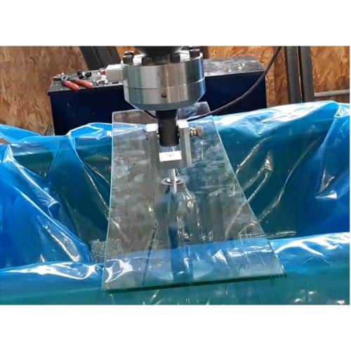
In some cases, curvature radius tests are conducted on the glass panels to ensure deformation limits of the glass at the attachment points. These tests help verify the maximum allowable local stresses at the attachment points. The following figure illustrates the conductance of curvature radius tests and a comparison of the results obtained through calculations.
In some cases, curvature radius tests are conducted on the glass panels to ensure deformation limits of the glass at the attachment points. These tests help verify the maximum allowable local stresses at the attachment points. The following figure illustrates the conductance of curvature radius tests and a comparison of the results obtained through calculations.
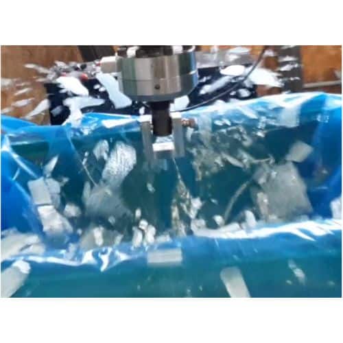
In order to verify the relevance of the calculation models, a test comparison can be carried out to measure the differences between reality and the model. The following picture shows the comparison between tests and calculations:
In order to verify the relevance of the calculation models, a test comparison can be carried out to measure the differences between reality and the model. The following picture shows the comparison between tests and calculations:
")
In addition to enabling the reduction of glass thicknesses, stress visualization helps design fittings and supports that are suitable for various projects (glass railings, structural glass, cladding, point fixings, etc.).
In addition to enabling the reduction of glass thicknesses, stress visualization helps design fittings and supports that are suitable for various projects (glass railings, structural glass, cladding, point fixings, etc.).
The visualization of stresses not only makes it possible to reduce the thicknesses of glazing, but also to design the most suitable fixings and supports possible for projects.
The visualization of stresses not only makes it possible to reduce the thicknesses of glazing, but also to design the most suitable fixings and supports possible for projects.
If you would like to learn more about AEG façade design and dimensioning, our technical sales teams are at your disposal.
If you would like to learn more about AEG façade design and dimensioning, our technical sales teams are at your disposal.